velotrain Posted February 11, 2016 Share Posted February 11, 2016 Well - against medical advice I've decided to separate the two units of my Blue Thunder engine so I can use them on either end of a ballast train. Das Steinkopf pointed me to a video showing how to remove the body shell, and I've made some progress from there, but am uncertain about the next few steps. My basic thought is to remove the drive shaft on the B unit, so the wheels may turn freely. I have realized that I could purchase the Kato motor chassis and have two powered sections, but I don't need that here and just want to create a "dummy" unit that will roll freely. By this time I've become familiar with Kato's approach to restraining tabs, but can't locate those holding the remaining plastic cover over the drive shaft. I can tell the general locations by where this piece resists coming off the chassis, but so far I haven't been able to spot the actual tabs restraining it, which means I don't know where I need to apply pressure - and in what direction. There seem to be a pair of tabs on each end. I want to remove the drive shaft, but don't know if I can simply lift it out once I've removed the remaining plastic cover. What concerns me are the sections at the ends of the worm gears - except where the cardan shaft had joined from the A unit. These may just slide up with some pressure, but since I haven't tried it yet I don't know. I suspect this - like the truck mounting, is very similar if not exactly the same on most / all Kato engines. I'm not sure I actually need to do it for this operation, but wondered how the trucks are removed? I can see tiny metal tabs that ride in the open plastic rectangle, but think this is just to control the pivot. Lightly grabbing the truck, it feel like there is something else restraining it. I haven't made a decision about couplers yet. There is a square "tube" in the truck that is at the right height, but the pinion gear only allows a couple of mm clearance. I may need to build a platform extension on the chassis, and body mount the coupler - likely MT; since these units will be mostly assigned to work trains, I may be able to justify a short platform with a railing, to facilitate passage by crew members between the engines and the work cars. I suppose another option would be to find a styrene shape of a similar size to the "tube", and graft it on - although, I suspect Kato uses a very slippery plastic here. I also need to do some plastic surgery on the body shell to cover where the original connections were between the two units, and simulate end doors. Link to comment
Das Steinkopf Posted February 11, 2016 Share Posted February 11, 2016 Hello Charles I haven't touched that end of the loco but I assume it would be like pulling out the motorized section, it requires some firm presssure as you gently wiggle it out of position. The drive shaft shouldn't be much of an issue as it has a worm gear either side akin to the ones in the motorized section of the locomotive, have a look at the photo's I have up and you will see them in it. Link to comment
Guest Closed Account 1 Posted February 12, 2016 Share Posted February 12, 2016 Even with removing the driveshaft you still have the gears causing drag. Try it and see how easy it goes first. You may end up removing the extra gears for free wheeling. Each truck can be released from the chassis with the little grey loops. Go gentle. The grey saddle (motor mount) snaps off, the trucks snap off. Be polite, just gently pull it straight up. Add a DCC decoder to it and speed match the two locos. Link to comment
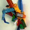
velotrain Posted February 12, 2016 Author Share Posted February 12, 2016 Even with removing the driveshaft you still have the gears causing drag. Try it and see how easy it goes first. Add a DCC decoder to it and speed match the two locos. I was able to figure everything out last night, so I'm all set. The worm gears came out with the driveshaft, and it now rolls very freely - the gearing in the trucks is a non-issue. The whole point of this was to end up with only the A-unit powered, so I'm not understanding the "two locos". Besides, I'm a DC kind of guy. Link to comment
Guest Closed Account 1 Posted February 12, 2016 Share Posted February 12, 2016 2 Locos, 2 motor cars, etc. meaning the 2 EH200's Glad you got it sorted out. Link to comment
velotrain Posted February 12, 2016 Author Share Posted February 12, 2016 Just one EH200 - that I've bashed into a powered A unit, and a dummy B unit. These will sit at the ends of a bashed HoKi 10000 ballast train. Link to comment
Recommended Posts
Create an account or sign in to comment
You need to be a member in order to leave a comment
Create an account
Sign up for a new account in our community. It's easy!
Register a new accountSign in
Already have an account? Sign in here.
Sign In Now